How to build the TLS1001 Kit
This kit has small parts and is not for children. Small electronics and engineering skills are needed in order to complete a build using this frame. This kit is designed to make the build process easier, but unfortunately it is still a very difficult process. Proceed at your own risk!
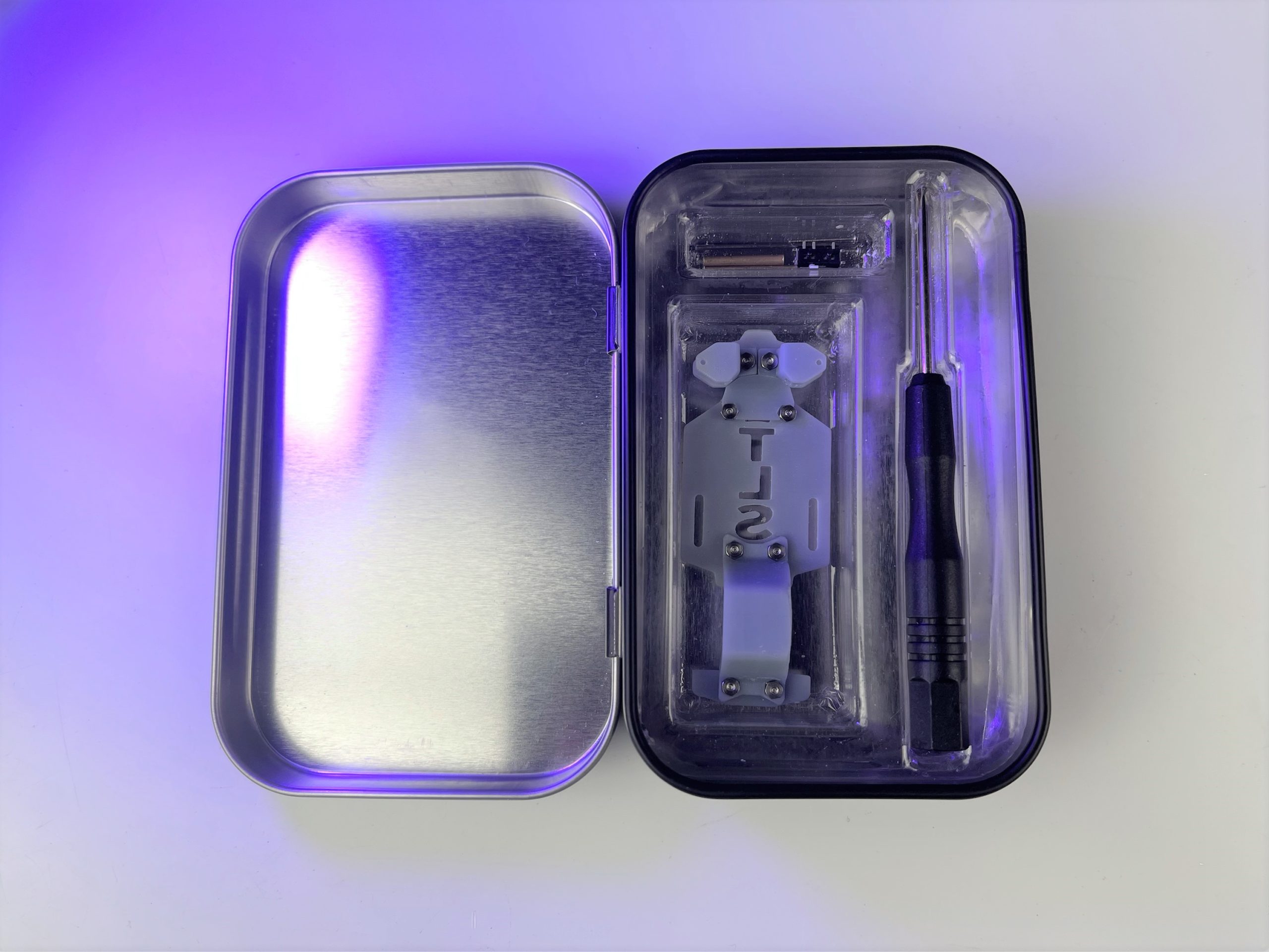
What’s Included:
- 1 TLS metal storage box
- 1 screwdriver
- 1 Frame (rear piece, motor arch, base plate, steering plate/steering arms, and 8 nuts/8 screws)
- 2 steering arm ends
- 1 steering arm connector
- 2 steering “L” pins
- 2 brass rods
- 6 rubber grommets
- 1 micro 2 position/3 prong switch
- 4 magnets
- Extra tubing and rods
Important base frame Information and tips
The frame itself is made of very brittle resin; when working with this kit, DO NOT put pressure on the resin frame. When gluing items to the frame, support the frame from both sides before applying a small amount of pressure. When tightening screws, do not overtighten! Stop as soon as you feel resistance, or else you might crack the resin. I’m working on different materials for the frame in the future!
Work over a clean table! If you manage to drop any small screws or other small parts it will be much easier to find them.
I have a wiring kit if you just need a small amount for a build or two.
Use a battery 80mah or higher at a minimum, preferably even 100mah or higher if you have room.
I use the Eflight USB charger for 1 cell batteries.
I use superglue exclusively on my builds.
Plastic wheels/tires are much easier to drift with if you are making a drift build.
YouTube video
You can watch the YouTube video here or below:
Adjusting the frame

When moving/sliding parts of the frame to change size for different car bodies, do not pull or push the frame as the screws have a tight fit. You can wiggle the screws with a screwdriver to get them to slide, or you can very carefully open up the slots for the screws with sandpaper or a hobby knife. Over time and use, the slots will become easier for the screws to slide in, which is why the parts slide so easily in my YouTube video. If needed, the screws can be completely removed and placed in a different position, just be careful not to lose them! When tightening the screws do not overtighten them! Stop as soon as you feel resistance to prevent the resin from cracking under pressure. You should have no issue getting the screws tight enough to keep everything solid without hurting the frame.
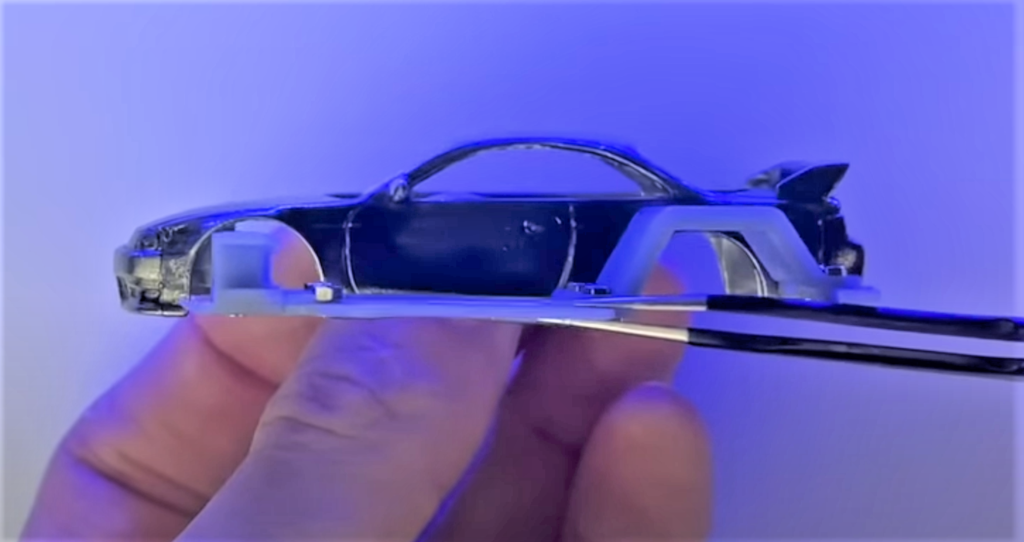
You’ll want to make sure the area for the rear axle and the front steering are lined up with the wheel wells. They need to be close, but don’t have to be perfect as the front steering can be slightly adjusted by loosening the screws and rotating them forwards or backwards and the rear motor/axle holder has a little extra room to adjust when placing the motor.
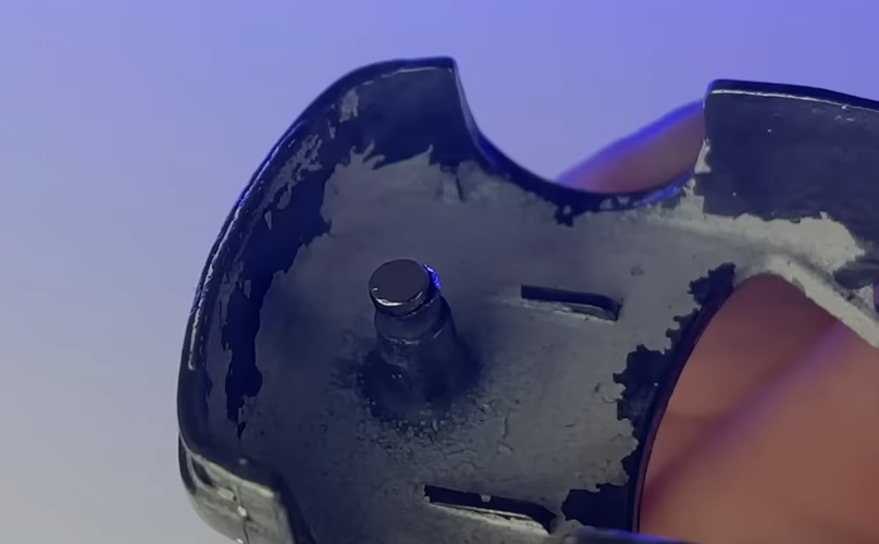
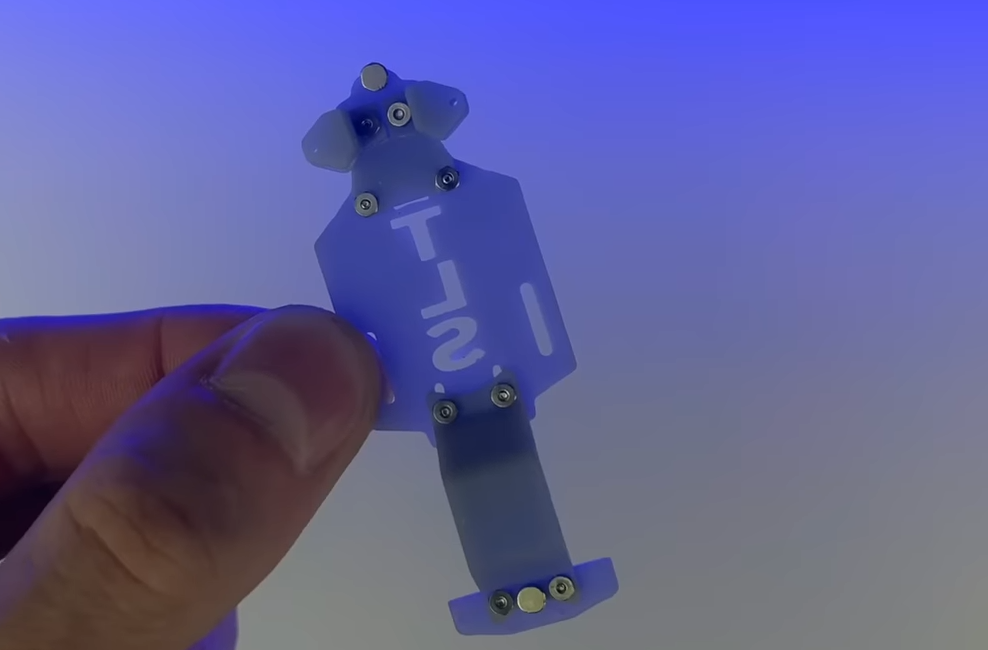
At this point you’ll want to figure out how you’re going to mount the frame to the body. The way I did it in the video was to glue magnets to the rivets on the car, and on the frame. If the rivets on your car are poorly positioned, you can either cut them off and re-glue them in a better position, or instead just remove the rivets all together and try placing the magnets somewhere else where the body and frame meet. Sometimes, I skip the magnets altogether and just add extra width to the frame with styrene until it’s wide enough to pressure fit into the body; this method must be done with extra care to keep from putting too much pressure on the brittle resin.
Steering assembly
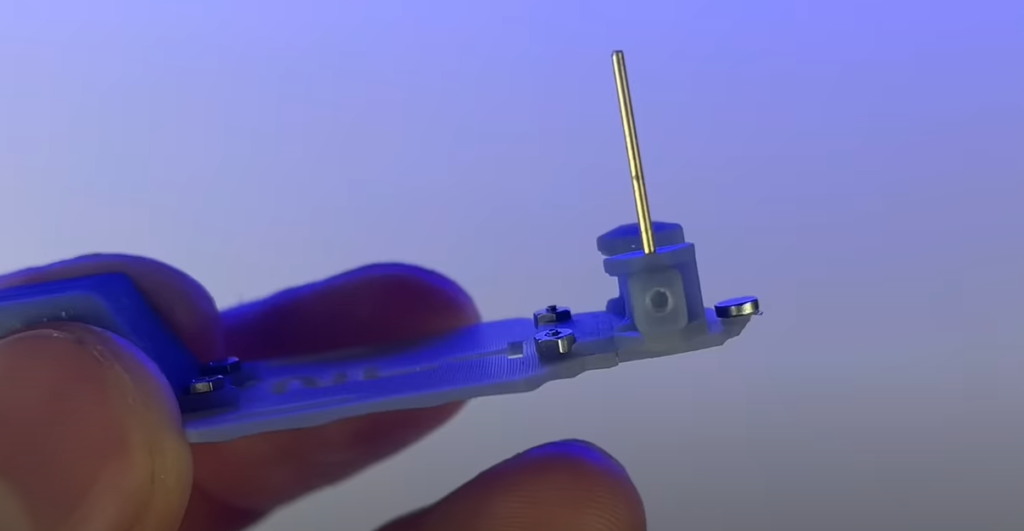
Take one of the small steering blocks and place it into the steering assembly; if the block is too tight, you can slightly sand the top and bottom of the block until it fits easily. Secure it with one of the brass rods supplied in the kit. If you have trouble getting the brass rod to go through the holes in the assembly, use a pointy knife such as the X-acto #1 blade to open the holes up; do this by placing the point of the blade in the hole and gently twisting 360 degrees(not back and forth). If you have a 0.8mm drill bit, you can use that to open up the hole instead. I recommend you just use one of the brass rods to do both sides, that way you can use the other supplied brass rod later on. One rod has enough length to do both sides if you cut it carefully. In the video I use a Dremel to cut the excess brass off, but if you don’t have that you can simply mark the rod where to cut, and then pull it out and cut it with cutters, or even just bend it back and forth on your line until it breaks.
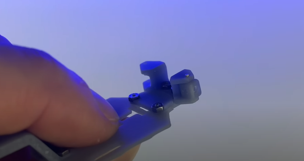
Before placing a small drop of glue on top the rod where it meets the resin frame, you’ll want to make sure the steering block is facing the right way. The skinny side with a hole in the center should be facing outwards, and the thicker side with a hole should be facing towards the rear of the frame (it’s facing my finger in the photo).
Once installed, if the block is stiff and hard to rotate, try gently rotating it back and forth to loosen it up. It should be free to rotate without much pressure.

Take one of the small brass tubes and place it into the steering block. You can angle this tube up or down to adjust the camber. Once you like the position, place a drop of superglue on the edge of the tube where it meets the resin steering block in order to secure it in place.
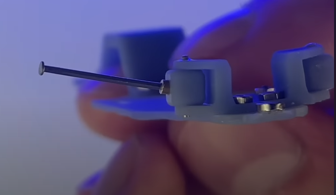
I used a spare axle and placed it into the tube to adjust the camber more easily. This is also how the axle will be placed and glued once the wheel is on.
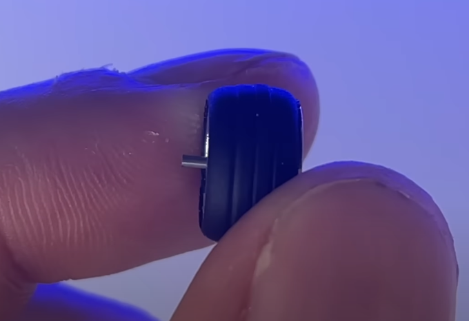
You’ll want to cut the axle just long enough to fit into the brass tube. Test fit the wheels into the brass axles. If you find that your wheels are sticking out past the body, and the frame is already adjusted to the minimum distance, you can try removing the wheels and grinding off some of the brass axle sticking out; you can also get skinnier wheels, or cut some material off of the back of your own like I did in this video(0:57 mark).
If all is well, place a small amount of glue inside the brass tube and insert the wheel/axle.
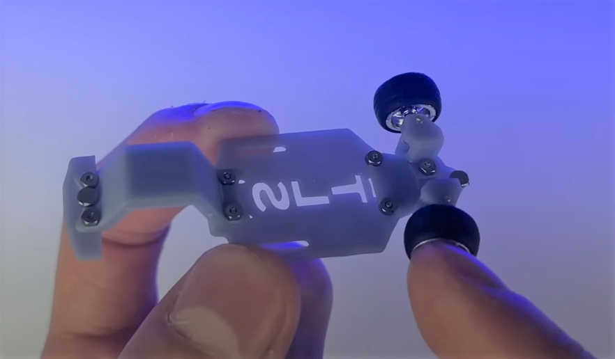
The wheels should be able to freely spin, and rotate with the steering. If you accidently get glue on the wheel and it becomes stuck to the axle, unscrew the steering arm and remove it; once removed, turn your wheel while holding the arm firmly but very carefully. This part is fairly strong compared to the rest of the frame, but it is still brittle. Once you do this, either the wheel will break loose from the axle, the axle will break loose from the brass tube, or the brass tube will break loose from the steering block. In whatever scenario, you should be able to start over from this point and retry gluing everything. If for some reason something breaks, I will have spare parts available soon. Small amounts of glue will help prevent this from happening.
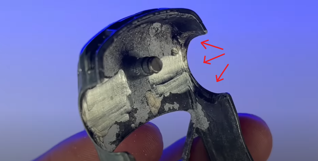
To make sure there is enough room for the wheels to turn, I recommend that you carefully grind out the inner fender if possible. If you’re new at this, practice on a different casting first.
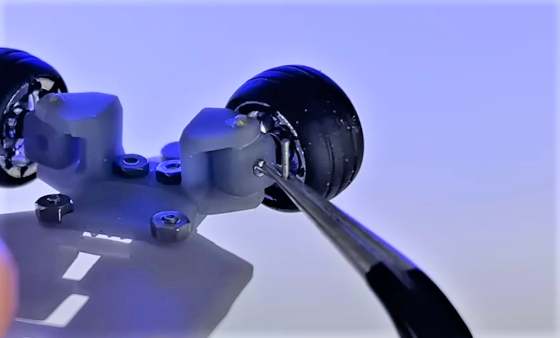
Next you’ll want to place one of the supplied L brackets into the hole on the steering block. Make sure it is placed perfectly at a 90 degree angle as pictured. If this bracket is leaning side to side, or tilted forward or back, it will cause stress on the steering and even steering failure.
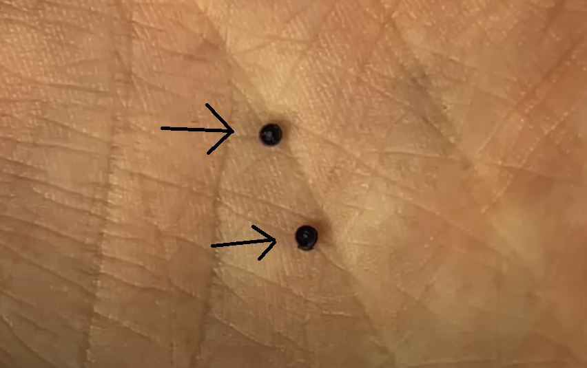
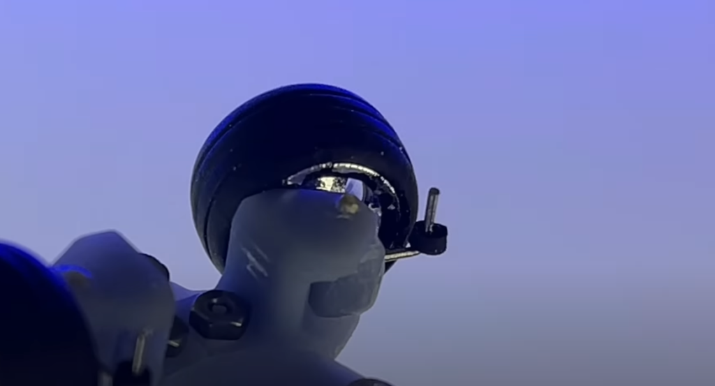
Next, place two of the six included O-rings onto the L brackets. These O-rings have a very small hole in the center that is hard to see. You’ll have to pressure fit it on to the bracket. Make sure to hold the underside of the bracket to relieve pressure while doing this, that way you don’t snap it off. 2 of the O-rings are extras, so if one is damaged or the hole is not centered for some reason, you can try another.
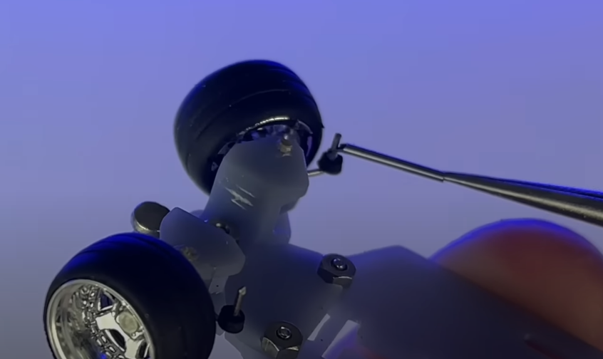
Next, attach the included steering ends, with the bent side facing down.
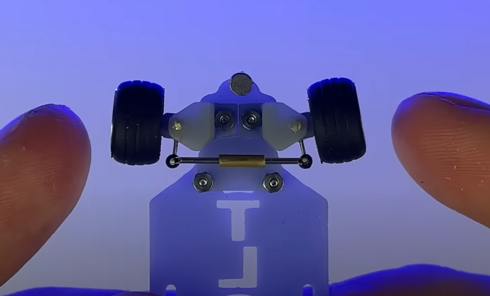
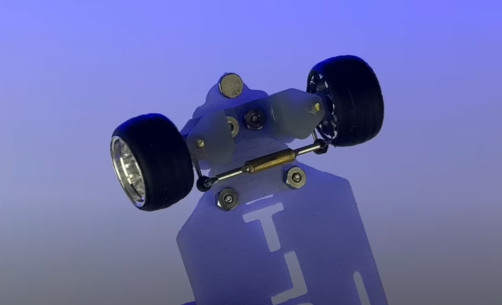
Use the smaller brass tube that’s included to connect the two arm ends. Before gluing, make sure the amount of toe in or out is acceptable. Generally, more toe in gives you more stable turns but less steering angle, while toe out gives you less control but more steering angle. I opt for more angle since the Radiolink receiver I use has a gyro to correct loss of control.
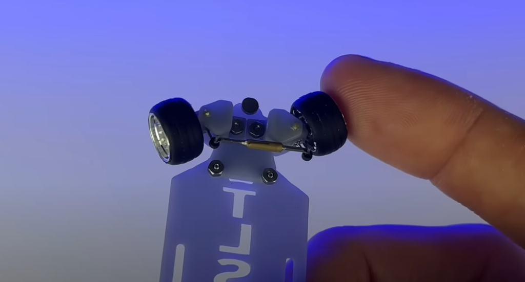
Apply a small amount of glue where each steering end meets the brass tube. You should now be able to steer the wheels manually. If the steering feels stiff or won’t turn, check for these issues:
- L brackets not perfectly 90 degrees to the horizon
- Steering blocks are too stiff and need to be loosened up by sanding or manually turning them back and forth
- Steering arms are somehow stuck on the L brackets or O-rings
- Steering arm is colliding with the frame
Rear motor

This dual shaft motor was in mind when the frame was designed, although you could probably also manage to mount a number of different motors to the frame such as this one with a little more torque. To get an idea of how that one could be mounted, check out this video(3:41 mark).
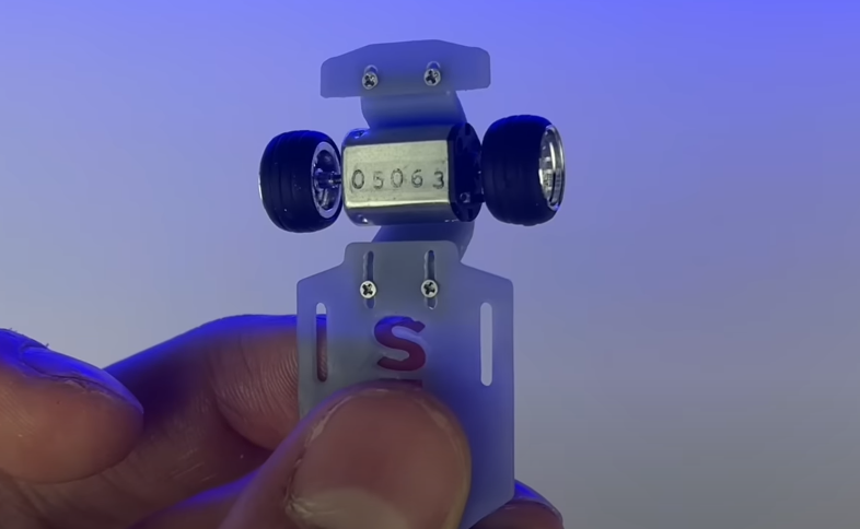
Simply put a small dab of glue on one of the motors flat sides and attach it to the frame, keeping the wheels straight and parallel with the frame. If the wheels end up slightly crooked, you can loosen the rear frame screws and adjust a bit.
Other Electronics and Wiring
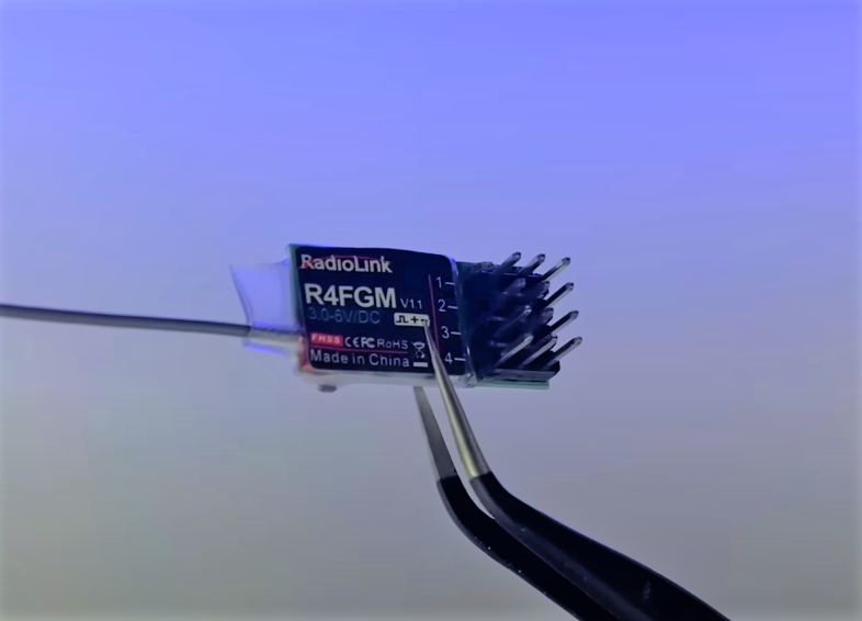
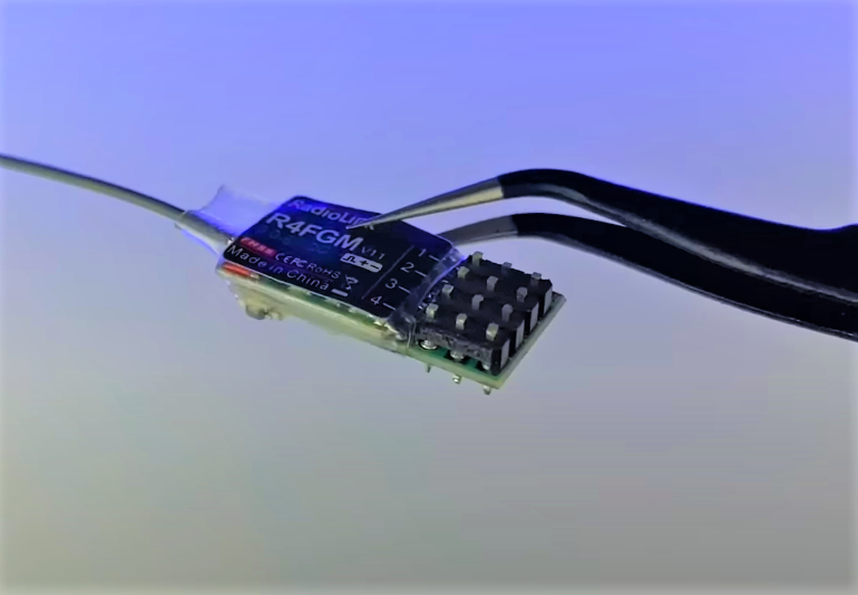
You can use a range of receivers in this build, but I personally like to use the Radiolink R4FGM because of its size and gyro abilities. Regardless, if your receiver has pins for each channel, you’ll want to cut them off to save room; just make sure to leave enough left for soldering wires to.
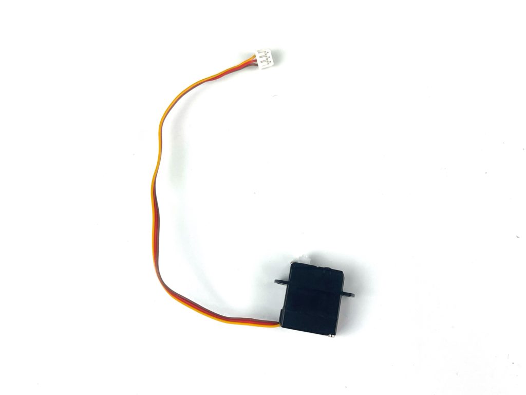
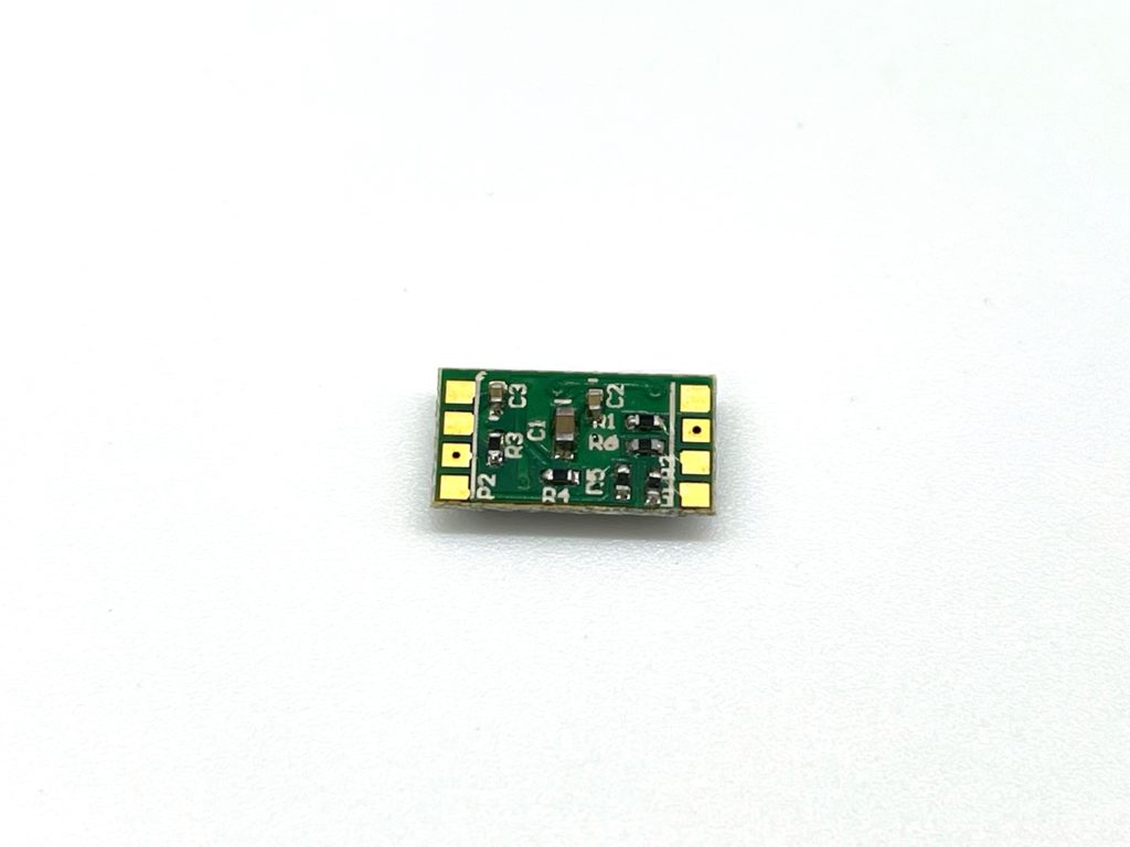
For the other electronics, the 1.7 gram servo and DasMikro 1S3A esc fit nicely into this frame.
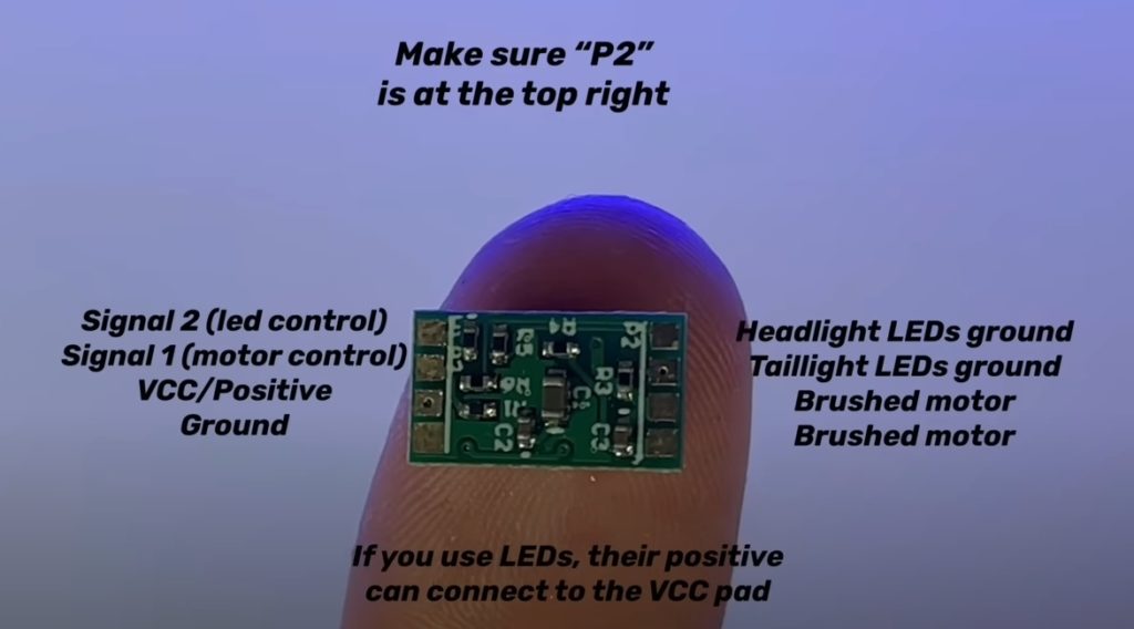

The only difference in the diagram above and the wiring in my video is that I used a different JST 1.25 connector for the charge plug. It really doesn’t matter, as long as the plug you use can be plugged into your charger. If you decide to put LEDs in your car, the top left pad on the ESC can be connected to the CH3 signal(left side) pin on the receiver for control and the LEDs negative wires can be connected to the upper right pads on the ESC, top for headlight LEDs, bottom for taillight LEDs. Your LEDs positive wires can be connected to any middle pin on the receiver(+ pins) or even to the VCC pad on the ESC along with the other wire we’ve already connected.
The way the switch works, is that when it is slid to the left, the left and center pin are connected; when it is slid to the right, the right and center pin are connected. We put the battery in the center because no matter what, we will be needing the battery involved. Wired as shown, when the switch is to the left the battery will be sending power to the receiver and when it is slid to the right the battery will disconnect from the receiver and connect to our charge plug, allowing us to turn the car off, and also charge it while it is off.
Binding
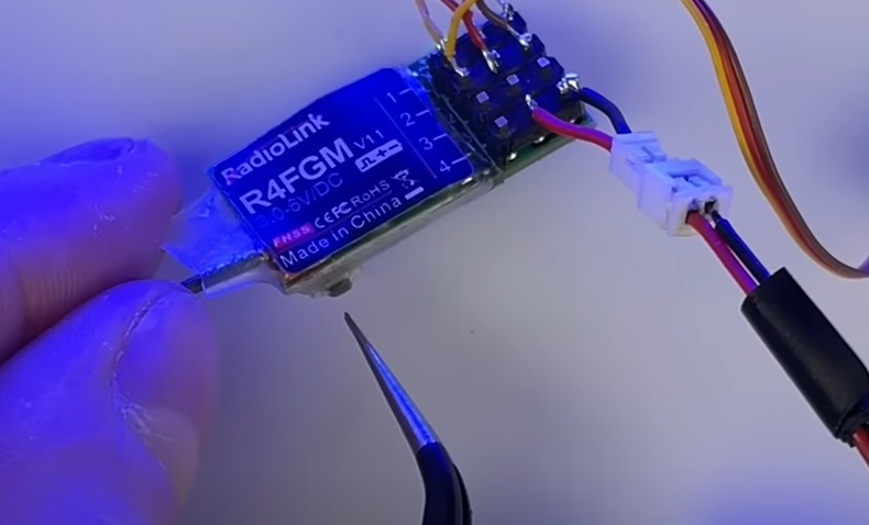
Once you get everything connected, test it all out first. If your receiver is not bound to your transmitter, you’ll need to do so now. Power on the circuit and the receiver should be slowly flashing. Hold the bind button on the receiver(shown in above photo) until it begins to quickly flash, then simply turn on the transmitter. If the light goes solid on the receiver, then it was successfully bound. You can now test if the steering servo and motor respond to inputs. If you installed LEDs, you’ll want to setup your ch3 to an aux switch. I will have a detailed radio setup page soon if you need help with that.
Mounting
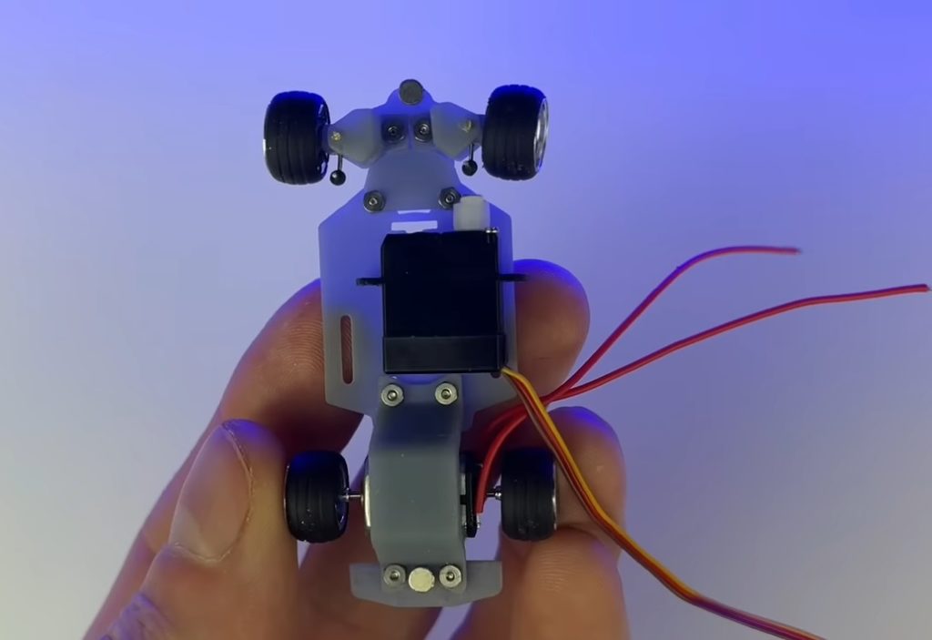
I like to place the servo to where the arm is just missing the bolt on the steering assembly, and the back of the servo is against the rear frame motor mount. For most builds, it’s okay if the servo is hanging off the edge a little, just make sure that the servo arm is not in the way of your steering, or wheel when it is at its max turning angle.

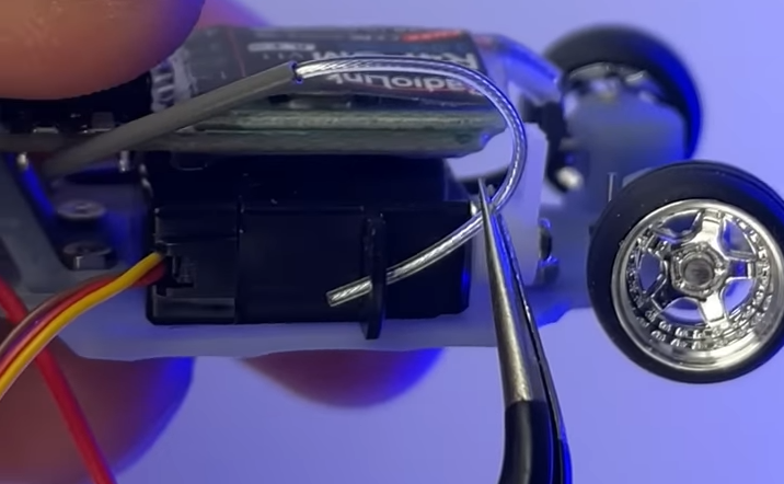
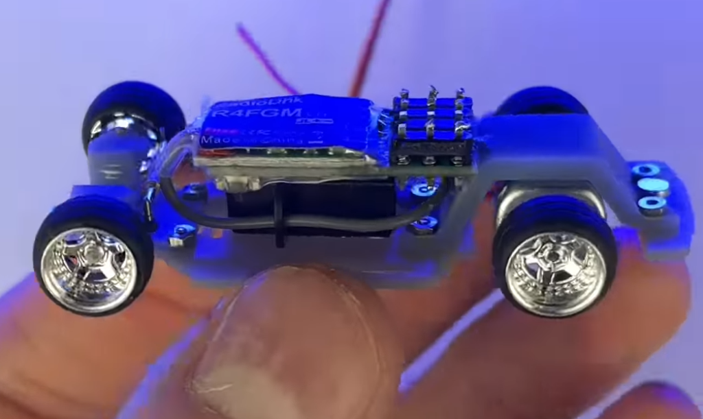
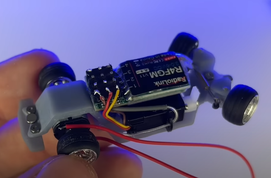
I mounted the receiver on top of the servo, centered to the frame, and as far back against the rear frame motor mount as it could go. Then I very carefully bent the antenna down and threaded it through the servos mounting holes to keep it neat and out of the way.
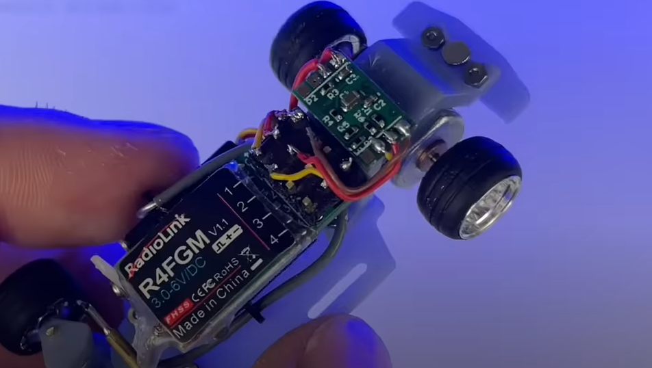
I mounted the ESC on top of the rear frame motor mount, but if you don’t have enough room in your build you could try placing it on top of the receiver, or anywhere else that it will fit.
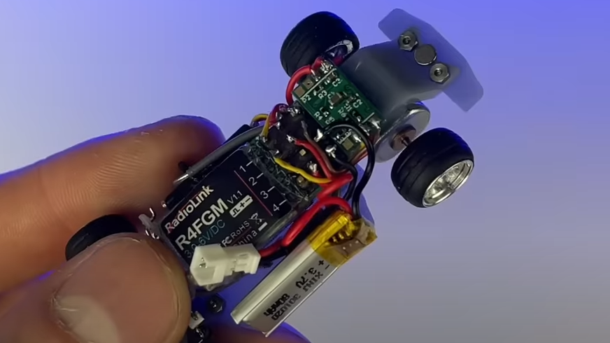
If you have a small enough battery, you can mount it on the side of the frame. My battery was a 301020, but I will warn that any battery under 100 mah must be in great shape and be a quality battery, otherwise they tend to “brownout” or randomly cut off due to low voltage output, even when fully charged.

The extra slots in the frame are to allow for access to the switch, as shown above. The switch included in the kit is difficult to mount without getting superglue into the switch itself. I recommend very small dabs of glue at a time, and only apply them to the metal part of the switch. If you find the switch easily breaking off, sand the metal a bit so that the glue has something to grab onto.
Connecting the Servo to the Steering
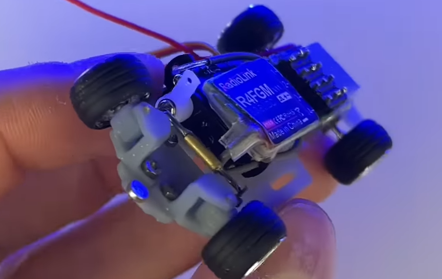
To make sure the servo arm has enough room to move, I cut off the last few holes on the arm and bent the antenna of the receiver out of its way as I stated earlier. If you do this, you must be very careful and bend it slowly as it is very difficult to fix the antenna if it breaks off at the receiver.
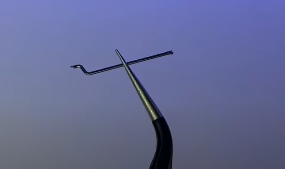
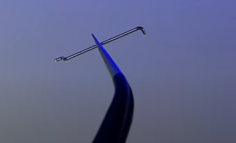
Either use the extra brass rod you have, or any other similar sized rod (like a paperclip, pin, etc.) as the connecting arm from the servo to the steering arm. To do this, first start by bending an “S” in one side, and then a perpendicular 90 degree bend in the other.
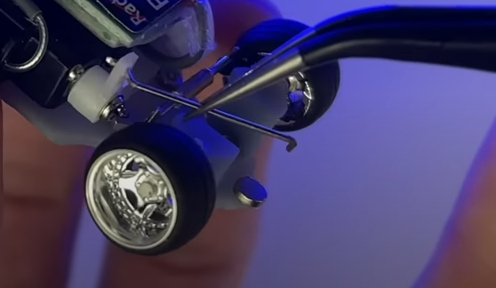
Make sure that the “S” end fits into the servo arm nicely.
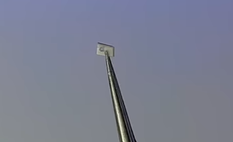
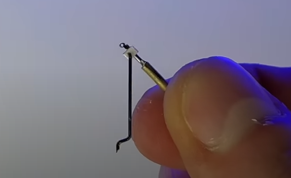
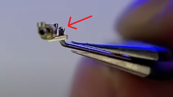
Cut a rectangle out of styrene and put a hole in it just big enough for the connecting rod to slide through. You can use a hobby knife to make this hole, or a .8mm drill bit. Glue the rectangle to the steering arm, on the far side from the servo when it’s mounted. Put the 90 degree side of your connecting arm into the styrene, and then put a blob of glue on the end; you can harden it faster with baking soda, or accelerator made for superglue.

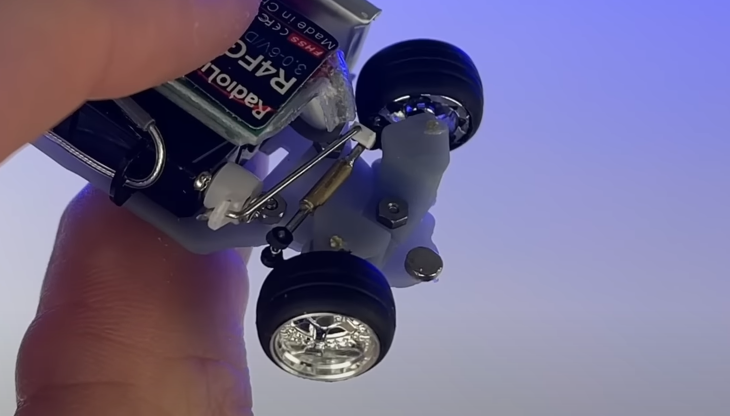
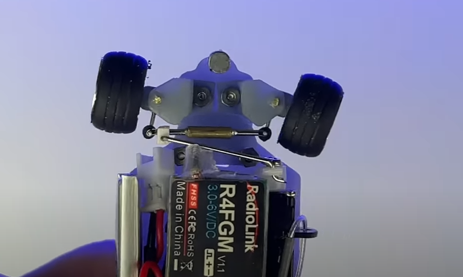
Place the “S” end of the connecting arm into the servo arm, and then place the steering arm back on; secure it with 2 of the supplied O-rings. At this point, turn on the car and test the steering. you might need to limit the steering through the radio if it’s causing a bind in anyway when maxed out.
Finishing up
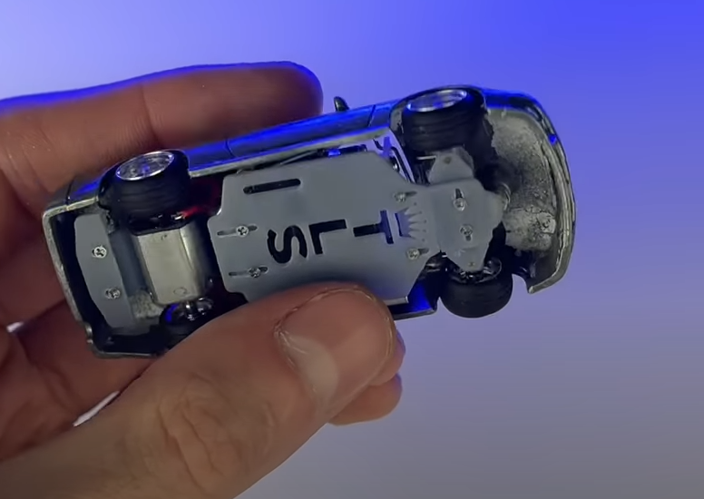
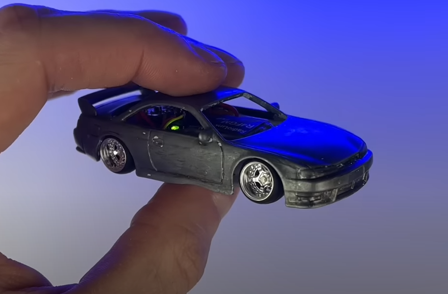
Make sure everything has good clearance and is working properly, if so you’re done! If you are painting it yourself, I’d recommend waiting until this point to avoid hurting the paint during testing.
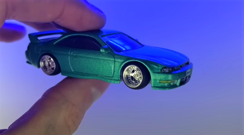
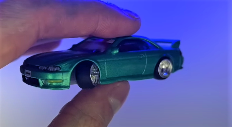
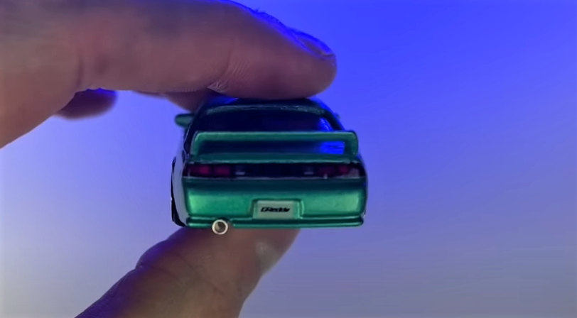
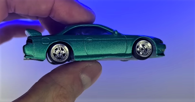
If you successfully got your RC working, congratulations! Please DM me your build on Instagram, or send it to TheLastSuperGarage@gmail.com
If you managed to break any pieces of the frame, the resin can usually be superglued back together with good luck, otherwise replacement parts will be for sale within a few days!

